Copper Welding Procedures
Introduction
Copper and Copper alloys are important engineering materials because of their good electrical and thermal conductivity, corrosion resistance, metal-to-metal wear resistance and distinctive aesthetic appearance.
Copper and most copper alloys can be joined by welding, brazing, and soldering. In this section, we talk about the different copper alloys and give some guidance about how to join these metals without impairing their corrosion or mechanical properties and without introducing weld defects.
Major groups of copper alloys
Pure Copper: 99.3% minimum Copper content.
Copper is normally supplied in one of three forms:
- Oxygen-free copper
- Oxygen-bearing copper (tough pitch and fire-refined grades) - the impurities and residual oxygen content of oxygen-bearing copper may cause porosity and other discontinuities when these coppers are welded or brazed
- Phosphorous deoxidized copper
High Copper Alloys: (a) Free machining copper - Low alloying additions of sulfur or tellurium can be made to improve machining. These grades are considered to be unweldable due to a very high susceptibility to cracking. Free machining coppers are joined by brazing and soldering.
(b) Precipitation - hardenable copper alloys - Small additions of beryllium, chromium or zirconium can be added to copper and then given a precipitation hardening heat treatment to increase mechanical properties. Welding or brazing of these alloys will over-age the exposed area resulting in degradation of mechanical properties.
Copper-Zinc Alloys (Brass): Copper alloys in which zinc is the major alloying element are generally called brasses. Brass is available in wrought and cast form, with the cast product generally not as homogeneous as the wrought products. Additions of zinc to copper decreases the melting temperature, the density, the electrical and thermal conductivity and the modulus of elasticity. The additions of zinc will increase the strength, hardness, ductility and coefficient of thermal expansion. Brasses can be separated into two weldable groups: low zinc (up to 20% zinc) and high zinc (30-40% zinc). The main problems encountered with brass is due to zinc volatilization which results in white fumes of zinc oxide and weld metal porosity. The lower zinc alloys are used for jewelry and coinage applications and as a base for gold plate and enamel. The higher zinc alloys are used in applications where higher strength is important. Applications include automotive radiator cores and tanks, lamp fixtures, locks, plumbing fittings and pump cylinders.
Copper-Tin Alloys (Phosphor Bronze): Copper alloys which contain between 1% and 10% tin. These alloys are available in the wrought and cast forms. These alloys are susceptible to hot cracking in the stressed condition. The use of high preheat temperatures, high heat input, and slow cooling rates should be avoided. Examples of specific applications include bridge bearings and expansion plates and fittings, fasteners, chemical hardware and textile machinery components.
Copper-Aluminum Alloys (Aluminum Bronze): Contain from 3%-15% aluminum with substantial additions of iron, nickel and manganese. Common applications for Aluminum Bronze alloys include pumps, valves, other water fittings and bearings for use in marine and other aggressive environments.
Copper-Silicon Alloys (Silicon Bronze): Available in both wrought and cast forms. Silicon Bronzes are industrially important due to their high strength, excellent corrosion resistance, and good weldability. The addition of silicon to copper increases tensile strength, hardness and work hardening rates. Low silicon bronze (1.5% Si) is used for hydraulic pressure lines, heat exchanger tubes, marine and industrial hardware and fasteners. The high silicon Bronze (3% Si) is used for similar applications as well as for chemical process equipment and marine propeller shafts.
Copper-Nickel Alloys: The cupronickel alloys containing 10%-30% Ni have moderate strength provided by the nickel which also improves the oxidation and corrosion resistance of copper. These alloys have good hot and cold formability and are produced as flat products, pipe, rod, tube and forgings. Common applications include plates and tubes for evaporators, condensers and heat exchangers.
Copper-Nickel-Zinc Alloys (Nickel Silvers): Contain zinc in the range 17%-27% along with 8%-18% Nickel. The addition of nickel makes these alloys silver in appearance and also increases their strength and corrosion resistance, although some are subject to de-zincification, and they can be susceptible to stress corrosion cracking. Specific applications include hardware, fasteners, optical and camera parts, etching stock and hollowware.
Weldability of Copper and Copper Alloys
Welding processes such as Gas Metal Arc Welding ('GMAW') and Gas Tungsten Arc Welding ('GTAW') are commonly used for welding copper and its alloys, since high localized heat input is important when welding materials with high thermal conductivity. Manual Metal Arc Welding ('MMAW') of copper and copper alloys may be used although the quality is not as good as that obtained with the gas shielded welding processes. The weldability of copper varies among the pure copper grades (a), (b) and (c). The high oxygen content in tough pitch copper can lead to embitterment in the heat affected zone and weld metal porosity. Phosphorus deoxidized copper is more weldable, with porosity being avoided by using filler wires containing deoxidants (Al, Mn, Si, P and Ti). Thin sections can be welded without preheat although thicker sections require preheats up to 60°C. Copper alloys, in contrast to copper, seldom require preheating before welding. The weldability varies considerably among the different copper alloys and care must be taken to ensure the correct welding procedures are carried out for each particular alloy to reduce the risks of welding defects.
2.1 Weld joint designs for Joining Copper and Copper alloys:
The recommended joint designs for welding copper and copper alloys are shown in figures below. Due to the high thermal conductivity of copper, the joint designs are wider than those used for steel to allow adequate fusion and penetration.
Figure 1: Joint Designs for GTAW and Shielded Metal Arc Welding of Copper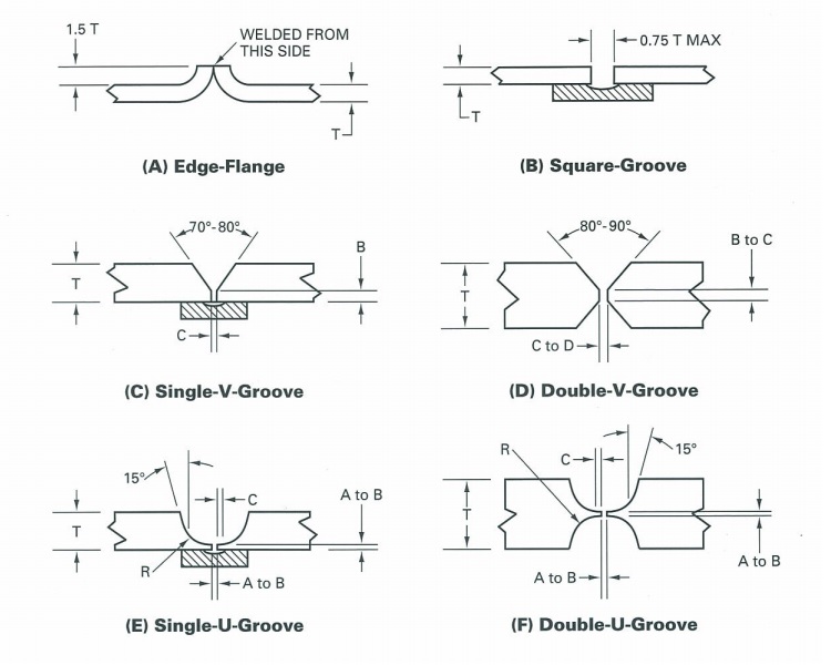 NOTE A = 1.6mm, B = 2.4mm, C = 3.2mm, D = 4.0mm, R = 3.2mm, T=thickness |
Figure 2: Joint Designs for GMAW of Copper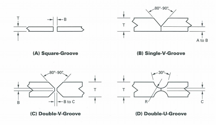 NOTE A = 1.6mm, B = 2.4mm, C = 3.2mm, R = 6.4mm, T=thickness |
2.2 Surface Preparation:
The weld area should be clean and free of oil, grease, dirt, paint and oxides prior to welding. Wire brushing with a bronze wire brush followed by degreasing with a suitable cleaning agent. The oxide film formed during welding should also be removed with a wire brush after each weld run is deposited.
2.3 Pre-heating:
The welding of thick copper sections requires a high preheat due to the rapid conduction of heat from the weld joint into the surrounding base metal. Most copper alloys, even in thick sections, do not require pre-heating because the thermal diffusivity is much lower than for copper. To select the correct preheat for a given application, consideration must be given to the welding process, the alloy being welded, the base metal thickness and to some extent the overall mass of the weldment. Aluminum bronze and copper nickel alloys should not be preheated. It is desirable to limit the heat to as localized an area as possible to avoid bringing too much of the material into a temperature range that will cause a loss in ductility. It is also important to ensure the preheat temperature is maintained until welding of the joint is completed.
Gas Metal Arc Welding (GMAW) of Copper and Copper Alloys
3.1 GMAW of Copper:
ERCu copper electrodes are recommended for GMAW of copper. Aufhauser Deoxidized Copper is a versatile 98% pure copper alloy for the GMAW of copper. The gas mixture required will be largely determined by the thickness of the copper section to be welded. Argon is generally used for 6mm and under. The helium-argon mixtures are used for welding of thicker sections. The filler metal should be deposited with stringer beads or narrow weave beads using spray transfer. Table 1 below gives general guidance on procedures for GMAW of copper.
Table 1: Typical Conditions for Manual GMAW
| Metal Thickness (mm) | Joint Design* | Electrode Diameter (mm) | Preheat Temperature | Welding Current (Amp) | Voltage Rate | Gas Flow Rate (l/min) | Travel Speed (mm/min) |
|---|---|---|---|---|---|---|---|
| 1.6 | A | 0.9 | 75°C | 150-200 | 21-26 | 10-15 | 500 |
| 3.0 | A | 1.2 | 75°C | 150-220 | 22-28 | 10-15 | 450 |
| 6.0 | B | 1.2 | 75°C | 180-250 | 22-28 | 10-15 | 400 |
| 6.0 | B | 1.6 | 100°C | 160-280 | 28-30 | 10-15 | 350 |
| 10 | B | 1.6 | 250°C | 250-320 | 28-30 | 15-20 | 300 |
| 12 | C | 1.6 | 250°C | 290-350 | 29-32 | 15-20 | 300 |
| 16 + | C, D | 1.6 | 250°C | 320-380 | 29-32 | 15-25 | 250 |
*refer to Figure 2
Recommended Shielding Gases for the GMAW of Copper and Copper Alloys:
- Welding Grade Argon
- Ar + >0-3% O2 or equivalent shielding gases
- Ar + 25% He or equivalent shielding gases
- He + 25% Ar or equivalent shielding gases
See Shielding Gas Guide for further details.
3.2 GMAW of Copper Silicon Alloys:
ERCuSi-A type welding consumables plus argon shielding and relatively high travel speeds are used with this process. Aufhauser Silicon Bronze is a copper based wire recommended for GMAW of Copper Silicon Alloys. It is important to ensure the oxide layer is removed by wire brushing between passes. Preheat is unnecessary and interpass temperature should not exceed 100°C.
3.3 GMAW of Copper Tin Alloys (Phosphor Bronze):These alloys have a wide solidification range which gives a coarse dendritic grain structure. Therefore care must be taken during welding to prevent cracking of the weld metal. Hot peening of the weld metal will reduce the stresses developed during welding and the likelihood of cracking. The weld pool should be kept small using stringer beads at high travel speed.
Gas Tungsten Arc Welding (GTAW) of Copper and Copper Alloys
Copper sections up to 16.0mm in thickness can be successfully welded using the GTAW process. Typical joint designs are shown in Figure 1. The recommended filler wire is a filler metal whose composition is similar to that of the base metal. For sections up to 1.6mm thick Argon shielding gas is preferred, while helium mixes are preferred for welding sections over 1.6mm thick.
In comparison to argon, argon/helium mixes permit deeper penetration and higher travel speeds at the same welding current. A 75% He/25% Ar mixture is commonly used to give the good penetration characteristics of helium combined with the easy arc starting and improved arc stability properties of argon. Forehand welding is preferred for GTAW of copper with stringer beads or narrow weave beads. Typical conditions for manual GTAW of copper is shown in Table 2 below.
Table 2: Typical Conditions for Manual GTAW
| Metal Thickness (mm) | Joint Design* | Shielding Gas | Tungsten Type & Welding Current |
Welding Rod Diameter (mm) | Preheat Temperature | Welding Current (Amp) |
|---|---|---|---|---|---|---|
| 0.3-0.8 | A | Argon | Thoriated/DC- | -- | -- | 15-60 |
| 1.0-2.0 | B | Argon | Thoriated/DC- | 1.6 | -- | 40-170 |
| 2.0-5.0 | C | Argon | Thoriated/DC- | 2.4 - 3.2 | 50°C | 100-300 |
| 6.0 | C | Argon | Thoriated/DC- | 3.2 | 100°C | 250-375 |
| 10.0 | E | Argon | Thoriated/DC- | 3.2 | 250°C | 300-375 |
| 12.0 | D | Argon | Thoriated/DC- | 3.2 | 250°C | 350-420 |
| 16.0 | F | Argon | Thoriated/DC- | 3.2 | 250°C | 400-475 |
*refer to Figure 1
4.2 Gas Tungsten Arc Welding of Copper-Aluminum alloys:
The ERCuAl-A2 filler rod can be used for GTAW of Aluminum Bronze Alloys. Alternating Current (AC) current with argon shielding can be used to provide an arc cleaning action to assist in removing the oxide layer during welding. Direct Current (DC-) electrode negative with Welding Grade Argon or Argon-Helium mixes can be used in applications requiring deeper penetration and faster travel speed. Preheat is only required on thicker sections.
4.3 Gas Tungsten Arc Welding of Silicon-Bronze:Aufhauser Silicon Bronze Rod (ERCuSi-A) can be used to weld Silicon Bronze in all positions. The Aluminum Bronze welding rod ERCuAl-A2 may also be used. Welding can be performed with DC-using argon or argon/helium shielding or AC using argon shielding gas.
Manual Metal Arc Welding (MMAW) of Copper and Copper Alloys
MMAW is normally used for the maintenance and repair welding of copper, copper alloys and bronzes. Aufhauser PhosBronze AC-DC electrode (ECuSn-C) can be used for the following:
- Minor repair of relatively thin sections
- Fillet welded joints with limited access
- Welding copper to other metals
Joint designs should be similar to that shown in Figure 1. Direct Current electrode positive (DC+) should be used with a stringer bead technique. Sections over 3.0mm require a preheat of 250°C or greater.
5.2 Manual Metal Arc Welding of Copper Alloys:Aufhauser PhosBronze AC-DC (ECuSn-C) can be used to weld Copper-Tin and Copper-Zinc alloys. Large butt angles are required and the weld metal should be deposited using the stringer bead technique.
Table 3: Recommendations for MMAW of Brasses and Phosphor Bronzes
| Copper Alloy | Recommended AWS Electrode Code | Aufhauser Welding Electrode | Electrode Polarity | Joint Design |
|---|---|---|---|---|
| Brasses | ECuSn-A or ECuSn-C | Aufhauser PhosBronze AC-DC | DC+ | C in Figure 1 |
| Phosphor Bronze | ECuSn-A or ECuSn-C | Aufhauser PhosBronze AC-DC | DC+ | C in Figure 1 |
Brazing of Copper and Copper Alloys
The principle of brazing is to join two metals by fusing with a filler metal. The filler metal must have a lower melting point than the base metals but greater than 450°C (use of a filler metal with a melting point less than 450°C is soldering). The filler metal is usually required to flow into a narrow gap between the part by capillary action.
Brazing is used widely for the joining of copper and copper alloys, with the exception of aluminum bronzes containing greater than 10% aluminum and alloys containing greater than 3% lead. Brazing of copper is used extensively in the electrical manufacturing industry, and in the building mechanical services and HVAC fields.
To achieve an adequate bond during brazing, the following points should be considered:
- The joint surfaces are clean and free of oxides, etc.
- The provision of the correct joint gap for the particular brazing filler metal
- The establishment of the correct heating pattern so that the filler metal flows up the thermal gradient into the joint
Standard solvent or alkaline degreasing procedures are suitable for cleaning copper base metals. Care must be taken if mechanical methods are used to remove surface oxides. To chemically remove surface oxides, an appropriate pickling solution should be used.
6.2 Joint Design Considerations:- The distance between the joints to be joined must be controlled to within certain tolerances which depend upon the brazing alloy and the parent metal used. The optimum joint gap typically lies between 0.04 and 0.20mm.
- Generally a joint overlap of three or four times the thickness of the thinnest member to be joined is sufficient. The aim is to use as little material as possible to achieve the desired strength.
Figure 3: Common Joint Design For Silver Brazing
|
6.3 Flame adjustment
Use a neutral flame. A neutral flame is where equal amounts of oxygen and acetylene are mixed at the same rate. The white inner cone is clearly defined and shows no haze.
6.4 Flux Removal:If flux has been used, the residue must be removed by one of the following methods:
- A Dilution in hot caustic soda dip
- Wire brushing and rinsing with hot water
- Wire brushing and steam
Braze Welding of Copper
Braze welding is a technique similar to fusion welding except with a filler metal of lower melting point than the parent metal. The braze welding process derives its strength from the tensile strength of the filler metal deposited as well as the actual bond strength developed between the filler metal and parent metal. Oxy-acetylene is usually preferred because of its easier flame setting and rapid heat input.
7.1 Choice of alloy:The alloy most suited to the job requirement depends on the strength required in the joint, resistance to corrosion, operating temperature and economics. Alloys commonly used are: Aufhauser Low Fuming Bronze or Aufhauser Low Fuming Bronze (Flux Coated).
7.2 Joint Preparation:Typical joint designs are shown in Figure 4 below.
Figure 4: Typical joint designs for Braze welding of copper
|
7.3 Flame adjustment
Use slightly oxidizing flame.
7.4 Flux:Use Aufhauser Copper and Brass Flux, mix to a paste with water and apply to both sides of joint. Rod can be coated with paste or heated and dipped in dry flux.
7.5 Preheating:Preheating is recommended for heavy sections only.
7.6 Blowpipe and rod angles:Blowpipe tip to metal surface 40° to 50°. Distance of inner cone from metal surface 3.25mm to 5.00mm. Filler rod to metal surface 40° to 50°.
Table 5: Data for the Braze welding of Copper
| Plate Thickness (mm) | Filler Rod (mm) | Blowpipe Acetylene Consumption (Cu. L/Min) |
Tip Size |
|---|---|---|---|
| 0.8 | 1.6 | 2.0 | 12 |
| 1.6 | 1.6 | 3.75 | 15 |
| 2.4 | 1.6 | 4.25 | 15 |
| 3.2 | 2.4 | 7.0 | 20 |
| 4.0 | 2.4 | 8.5 | 20 |
| 5.0 | 3.2 | 10.0 | 26 |
| 6.0 | 5.0 | 13.5 | 26 |
7.7 Welding Technique:
After preheating or after the joint is raised to a temperature sufficient to permit alloying of the filler rod and copper, melt a globule of metal from the end of the rod and deposit it into the joint, wetting or tinning the surface. When tinning occurs, begin welding using forehand technique. Do not drop filler metal on untinned surfaces. See Figure 5.
Figure 5: Braze welding forehand technique
|
7.8 Flux Removal:
Any of the following methods may be used to remove flux residue:
- Grinding wheel or wire brush and water
- Sand blasting
- Dilute caustic soda dip
Aufhauser Filler Metals
Aufhauser manufactures a complete line of alloys for your copper brazing and welding needs. We help you choose an appropriate copper welding alloy from our Selection Chart.


